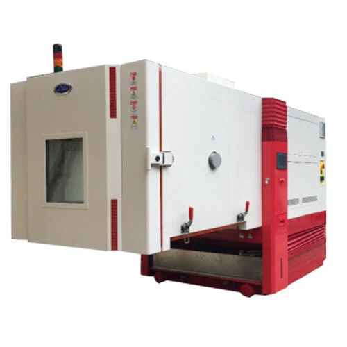
Environmental or Climatic Test Chamber has been developed for so many years.
Like development of other test equipment, the development of climatic test chamber is also following the requirement of the test standard, both common international test standard and test standard specially developed by specific industry (electronics, automotive, defence, packaging, etc).
Starting from small desktop chamber up to large walk-in chamber, from standard temperature chamber up to explosion-proof test chamber.
Based on type of controlled parameter, environmental test chamber can be classified into below:
Temperature and Humidity Test Chamber
a common environmental test chamber produced by manufacturer. The maximum temperature limit can go up to 150 - 200 degree C. While, the minimum temperature limit can go down to minus 20 – minus 70 degree C. Can be used for wide range of environmental test application.
Altitude, Temperature and Humidity Test Chamber
a combination of standard temperature humidity chamber and pressure-controlled chamber. For simulating airborne condition when pressure condition varies depending on the altitude level. Commonly done for device mounted in aerial vehicle.
Thermal Shock Test Chamber
an environmental test chamber that can simulate high temperature rate of change (thermal shock).
Rain, Sand, and Dust Test Chamber
an environmental test chamber used to perform "Ingress Protection" (IP) Rating test.
Vibration, Temperature and Humidity Test (AGREE) Chamber
an environmental test chamber that can be combined with Vibration Test System, to provide vibration, temperature, and humidity load simulation at the same time.
Based on the size of chamber:
Standard Size Test Chamber
for general size of UUT. The size range starts from 200 litres up to 1000 litres.
Desktop Size Test Chamber
for small size of UUT, such as small electronic components, chemical substances, pharmaceuticals, etc.
Walk-In Test Chamber
for large size of UUT, starts from small machine, up to whole vehicle unit.
Dual Test Chamber
very useful and efficient for 100 percent production quality check.
Based on Cooling System:
Air Cooled
commonly used for temperature rate of change up to 5 degree/min
Water Cooled
commonly used for temperature rate of change up to 15 degree/min
Nitrogen Cooled
commonly used for temperature rate of change higher than 15 degree/min
Like vibration testing that failure mode at the critical area may not be easy to identify and monitor, monitoring the failure mode that happens during temperature humidity test will be also challenging. Fatigue failure may also happen during temperature humidity testing, but thermal fatigue failure may become totally different and more challenging compare to structural fatigue failure.
In general, there are three types of fatigue components that influences thermal failure:
Thermal Fatigue
Thermal fatigue failure during cyclic temperature humidity testing may develop crack initiation and crack propagation at UUT, similar like structural fatigue failure. During cyclic temperature loading, each component of UUT will deform due to each material thermal expansion. Due to difference of thermal expansion and also mounting method (example: screw) that creates constraint to the deformation, stress/strain concentration will be formed. This cyclic stress/strain will lead to crack initiation and propagation that for long period may lead to thermal fatigue fracture.
Corrosion/Oxidation
Corrosion happens when there is chemical reaction (oxidation) between material and oxygen. In most structure, the material will be covered with coating surface to increase toughness against corrosion. But in some cases, when crack is already initiated and propagated, the coating layer may be open and increase the probability of corrosion to be formed and spread out. This corrosion layer will make the material become more brittle, reduce the toughness and also fatigue strength.
Creep
Creep is type failure that happens when material is subjected to a long duration constant stress loading at high temperature environment. At high temperature (still below the melting point) and constant stress loading (still below the material yield strength), the material structure may produce excessive deformation over long period of time. In some cases, the excessive deformation may cause a contact between components and cause further damage which is beyond acceptable level.


